Test generation for Finite State Machine
Step 1. Upload file with Finite state machine
About
FSM Tester integrates a number of original solutions in the area of test generation for (extended) Finite State Machines. It took us a while to finally collect various solutions together and we acknowledge the financial support by the Russian Science Foundation (RSF), project #16-49-03012 (scientific group of prof. Nina Yevtushenko), letting us to do this.
Original algorithms and methods incorporated into the FSM Tester have been previously published in:
- A. Kolomeez. Extended Finite State Machine based techniques for deriving tests for control systems, Tomsk< 2010 (Алгоритмы синтеза проверяющих тестов для управляющих систем на основе расширенных автоматов: диссертация на соискание ученой степени кандидата технических наук / Коломеец А.В. Томск, 2010. 129 с.)
- El-Fakih, K., Kolomeez A., Prokopenko S., Yevtushenko, N.: Extended finite state machine based test derivation driven by user defined faults. In Proc. of the IEEE International Conference on Software Testing, Verification, and Validation, ICST 2008, Lillehammer, Norway: pp. 308-317.
- R. Dorofeeva, K. El-Fakih, S. Maag, A. Cavalli, and N.Yevtushenko, "FSM-based conformance testing methods: a survey annotated with experimental evaluation", Information and Software Technology Journal, Elsevier, 2010 (52), pp. 1286-1297.
- A. Petrenko, N. Yevtushenko. Testing from partial deterministic FSM specifications. IEEE Trans on Computers, 2005, vol. 54 (9), pp. 1154-1165.
- Vinarskii, E., Laputenko, A., Deriving tests for digital systems at the lower and higher description level. Vestnik NSU. Vychislitelnaja technika, upravlenie I informatika, 2018, accepted for publication (Лапутенко А.В., Винарский Е.М. Синтез тестов для цифровых систем на высоком и низком уровнях абстракции. Вестник ТГУ. Вычислительная техника, управление и информатика, принято к публикации, 2018).
1 Some Examples of Finite State Machines (FSMs)
1.1 Deterministic Connected Minimal and Complete FSM
Consider the following transition diagram of an FSM which is deterministic connected minimal and complete:
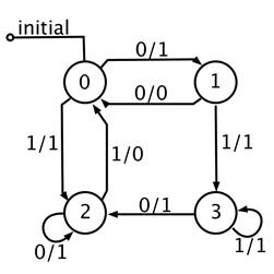
Its text description in the format .fsm is shown below (download)
    F 0         /* Fixed preamble */
    s 4         /* The number of states, it is four here*/
    i 2         /* The number of inputs, it is two here*/
    o 2         /* The number of the outputs , it is two her */
    n0 0        /* The initial state of the FSM */
    p 8         /* The number of transitions */
    0 0 1 1     /* A transition is a 4-tuple: starting state 0, input 1, end state 1 and output 1 */
    0 1 2 1     /* Another transition ... */
    1 0 0 0     /* ... */
    1 1 3 1     /* ... */
    2 0 2 1     /* ... */
    2 1 0 0     /* ... */
    3 0 2 1     /* ... */
    3 1 3 1     /* ... */
States, inputs and outputs are not necessary integers. Then the description of the previous example might be as follows (download):
    F 0
    s 4 START END CONNECT DISCONNECT	/* After the states’ number the list of the state names is given*/
    i 2 INPUT-1 INPUT-2                 /* After the inputs’ number the list of the input names is given*/
    o 2 OUTPUT-1 OUTPUT-2               /* After the outputs’ number the list of the output names is given*/
    n0 START                            /* The initial state  */
    p 8
    START INPUT-1 DISCONNECT OUTPUT-1	/* A transition is a 4-tuple: Starting state ‘START’, input ‘INPUT-1’, end state ‘DISCONNECT’ and output ‘OUTPUT-1’*/
    START INPUT-2 START OUTPUT-2
    END INPUT-1 START OUTPUT-2
    END INPUT-2 START OUTPUT-1
    CONNECT INPUT-1 START OUTPUT-1
    CONNECT INPUT-2 DISCONNECT OUTPUT-1
    DISCONNECT INPUT-1 CONNECT OUTPUT-1
    DISCONNECT INPUT-2 END OUTPUT-1
2 Other examples
2.1 Non-deterministic FSM
From the state 3 under the input action 1 there are two transitions (download).
    F 0
    s 4
    i 2
    o 2
    n0 0
    p 9
    0 0 1 1
    0 1 2 1
    1 0 0 0
    1 1 3 1
    2 0 2 1
    2 1 0 0
    3 0 2 1
    3 1 3 1
    3 1 2 1
2.2 Incomplete FSM
There is no transition from state 2 under input 1 (download).
    F 0
    s 4
    i 2
    o 2
    n0 0
    p 7
    0 0 1 1
    0 1 2 1
    1 0 0 0
    1 1 3 1
    2 0 2 1
    3 0 2 1
    3 1 3 1
2.3 Nonminimal FSM
States 1 and 3 are equivalent (download).
    F 0
    s 4
    i 2
    o 2
    n0 0
    p 8
    0 0 1 1
    0 1 2 1
    1 0 0 0
    1 1 3 1
    2 0 2 1
    2 1 0 0
    3 0 1 1
    3 1 2 1
2.4 Not connected FSM
State 3 is unreachable from the initial state 0 (download).
F 0
s 4
i 2
o 2
n0 0
p 9
0 0 1 1
0 1 2 1
1 0 0 0
1 1 3 1
2 0 2 1
2 1 0 0
3 0 2 1
3 1 3 1
3 1 2 1
1 Some Examples of Extended Finite State Machines
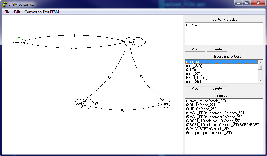
Consider the following transition diagram of an EFSM, which is deterministic, connected, minimal and complete:
Its text description in the format (EFSM text format for test generation download example.efsm, file for EFSM Editor download example.efsm_design):
| 2 4 6 2 2 3 1 0 | 2 (number of states) 4 (number of pairs input-state) 6 (transition number) 2 (number of inputs) 2 (number of outputs) 3 (number of context variables and parameters) 1 (number of context variables) 0 (initial state s0) |
| s0 | description of transitions at state s0 in the next unit (Unit 3) starts at Line 0 and has 2 lines |
| 0 2 | |
| s1 | description of transitions at state s1 in the next unit starts at Line 2 and has 2 lines |
| 2 2 | |
| 0 0 1 | description of transitions under input i0 (0) in the next unit (Unit 4) for transition 0 starts at Line 0 and has 1 transition |
| 1 1 2 | description of transitions under input i1 (1) in the next unit (Unit 4) for transition 1 starts at Line 1 and has 2 transitions |
| 0 3 1 | description of transitions under input i0 (0) in the next unit (Unit 4) for transition 2 starts at Line 3 and has 1 transition |
| 1 4 2 | description of transitions under input i1 (1) in the next unit (Unit 4) for transition 3 starts at Line 4 and has 2 transitions |
| true | transition 1: the predicate of transition from s0 under i0 |
| transition 1: updating context variables and output parameters (empty line = no update) | |
| 0 0 | transition 1: output (0); next state s0 (0) |
| w==0 | transition 2: the predicate of the first transition from s0 under i1 |
| w=w+x;y=w | transition 2: transition 0: updating context variable (w)and output parameter (y) |
| 1 0 | transition 2: output (1); next state s0 (0) |
| w~=0 | transition 3: the predicate of the second transition from s0 under i1 |
| y=w | transition 3: updating the output parameter (y) |
| 1 1 | transition 3: output (1); next state s1 (1) |
| true | transition 4: the predicate of transition from s1 under i0 |
| transition 4: updating the context variables and output parameters (no update) | |
| 0 0 | transition 4: output (0); next state s0 (0) |
| w==0 | transition 5: the predicate of the second transition from s1 under i1 |
| y=w | transition 5: updating the output parameter (y) |
| 1 1 | transition 5: output (1); next state s1 (1) |
| w~=0 | transition 6: the predicate of the transition from s1 under i1 |
| y=w | transition 6: updating the output parameter (y) |
| 1 0 | transition 6: output (1); next state s0 (0) |
| i0 | describing input i0 |
| 0 | number of i0 parameters (0) |
| i1 | describing input i1 |
| 1 | number of i1 parameters (1) |
| x | describing the input parameter x of i1 |
| 1 1 | Line number in the next unit (Unit 6) for describing x (1); interval number in x specification domain |
| 0 1 | interval [0, 1] |
| z0 | describing output z0 |
| 0 | number of z0 parameters (0) |
| z1 | describing output z1 |
| 1 | number of z1 parameters (1) |
| y | describing the output parameter y of output z1 |
| 2 | Line number in the next unit (Unit 6) for describing y (2) |
| w | context variable |
| x | input parameter |
| y | output parameter |
| w | context variable |
| 0 0 | the context variable w is described in Line 0; the initial value is 0 |
The service has a graphical editor; an EFSM can be drawn and converted into the above format for test derivation.